Maintenance Procedures
The point of Mr. Berg buying eight modules was that we could: one, resource parts, and two, replace entire modules in a repair time that allows programmers time to debug in the pit. Some might question the importance of removal and replacement times.. but programmers need to reassess new CAN ids when that happens, make sure the wheels rotate correctly, and obviously more. When programmers only have thirty minutes or less between matches, a high replacement time is the last thing they need. Remove stress. Remove complexity.
In this doc, I will go over every procedure you'll have to use through use of a swerve chassis. That includes the physical replacement and reassembly of parts as well as procedure on the field. Procedures on the field are extremely important because they limit extensive damage that happens from continued use of a module while it is approaching the "fatal error" phase.
- Watches - because time is so important, some things are not going to be immediately fixed. This might include metal shavings, hair and dust that accumlates in the wheels and gear wells. These are defined as watches.
- Fatal error - a swerve module is inoperable. This also implies that the chassis is incapable of rotating and translating at the same time, as is the nature of swerve. Due to this, all "auto placement" functions are disabled as well.
- Angle motor - the motor that drives the wheel rotation, usually can be 100% identified by being near the rotation bearing. Can also be identified by rotating the module and finding the motor by following the gear path.
- Drive motor - the motor that drives the wheel's translational speed. Located on the center bearing or by following the gear path.
The repair crew can be made up of at five people, with four working in pairs and one directing. They are not just randomly chosen, and can be swapped out with people that also have the proper training. They are in charge of diagnosing errors and checking each module when it comes into the pit, by following the diagnosis procedure. The Drive Team should also be repair crew worthy, because they may have to diagnose the most likely problems on the field, without direct access to the robot. This is also because it will save space by having people handle multiple roles (albeit seperate, field vs pit).
A person is quick repair qualified after they properly identify/produce each of the following in a test-like setting:
- Drill certification
- Proper recitation of correct sizing of hex key and nut drivers
- Knowledge of CAN bus topology
- Basic safety sense
- Complete replacement of a module in < 20 seconds
A person is deep repair qualified after they properly identify/produce each of the following in a test-like setting:
- All of quick repair qualifications are met
- Knows basic swerve module structure
- Knows the correct Nm of torque to torque motors with
- Can use loctite
- Has shown mastery of replacing both falcon motors in < 3 minute w/ prep
- Has memorized the placement of spacers & pinions on drive and angle motors
A person is director qualified after they properly identify/produce each of the following in a test-like setting:
- Both deep repair and quick repair qualifications are met
- Has extensive practice with swerve and has repaired it multiple times (only in practice)
- Direct approval required by Dave :)
For quick replacement repairs, the repair crew should have:
- Quick repair approval
- 2x 3/8 size nut drivers
- 2x 5/32 size hex keys (the red ones)
- 2x drills, can be torque or normal
- Previous experience disconnecting CAN wires.. (they are wires) These are used for both taking off and putting back on.
Procedure for quick replacement is as follows:
- Put the robot on the Robot cart.
- Disconnect all CAN wires to the broken module. There should be two CAN connectors with Ferrule connections. There should also be four powerpole crimped conncetions between the two motors of the module and the PDH.
- Assume positions.
- The hex key side is on top while the nut driver goes to the bottom of the assembly.
- This means that the person with the drill has to be under the robot cart.
- Remove the four screws that hold each module in place. Do not unscrew anything else.
- Retrieve the new module. It should have been prepared beforehand for quick installation.
- Place the module in the old one's place and then fasten the module with 3/8 bolts. New bolts should be installed every time a module is replaced if any signs of damage are found in the fastening system.
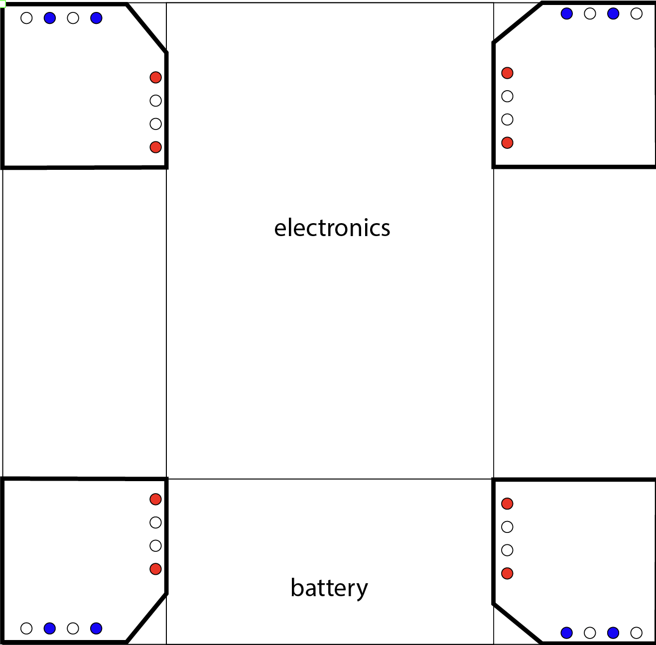
- The placement of the modules is shown to the right.
- The screws should be installed in the colored holes. Red and blue only signify whether it is facing electronics or not.
- Reconnect all CAN wires and powerpole crimps to return power to the motors.
- Notify programming.
- Programming Instructions
- Reevaluate CAN ids of the new motors. They might be the same, they might not be. The old CAN IDs should stay the same.
- Deploy the official 2023 code and inspect the absolute encoder values. Face the driver gear (the gear that is used to drive the wheel, not rotate it) towards you and see what value that returns on Shuffleboard. Put that value into the absolute offset located in the 2023 project. Also comment that it is a replacement module.
- Possible "testing" mode
- For director: Write down the module # that was replaced and the one that was put on.
For quick replacement repairs, the repairer (singular, only one operating at a time) should have:
- Deep repair approval
- 1x DeWalt Impact Driver
- Loctite 243
- New Falcon(s)
Procedure for falcon replacement is as follows:
- First, have the director on hand diagnose the problem. Determine which motor it is or if both need to be replaced.
- Take the to-be-repaired module in one hand, non-dominant and remove the module bolts which holds the motor plate against the module gears.
- The module body can be put to the side, as nothing will be done to it until reassembly.
- Take the motor plate, and Impact Driver.
- Find the screw that holds the Falcon to be replaced in to the motor plate. This screw is loctited to avoid it from coming loose during extensive use. The breakaway torque for Loctite 243, which is the loctite on these screws, is in the range of 20 to 25 Nm. The Impact Driver on speed two can make a max torque of 170 Nm @ 1000 RPM. It will definitely break at speed two.
Be careful of the driver when it is at speed two, because the torque increases from 27 Nm @ 1000 RPM all the way up to 170 Nm @ 2800 RPM.