How to make a Raspberry Pi Pico into a graphical PID controller. Runs using MicroPython.

- Raspberry Pi Pico with male headers (ideally short) and power supply
- Pico 0.96" LCD with buttons
- BME280 sensor breakout with I2C connection
- Jumper wires
- N-channel power MOSFET with logic-level gating (e.g., IRLB8721)
- DC power supply
- For lower-power heating (< 10 W) a Micro USB 2-way Y-splitter cable can be used from a Pi 3 USB power supply.
- For higher-power heating, a separate 12V power supply is recommended along with a female DC 2.1mm jack
- Resistive heating elements (e.g., an electric heating pad)
From left to right in the image below (heat sink at the back), the pins are gate, drain, and source.

- Connect the gate to the PWM output (default: GP0, pin 1).
- Connect the source to one of the Pico's ground pins.
- Connect the drain to one of the resistive heater's connectors.
- Connect the positive (red) line from the power supply to the other connector on the resistive heater
- Connect the negative (black) line from the power supply to one of the Pico's ground pins
If not already in place, headers need to be soldered to the BME280 breakout, then connecgted with jumper wires. Adafruit and others sell a BME280 breakout with STEMMA QT connections.

The Pico pinout is given in the image below.
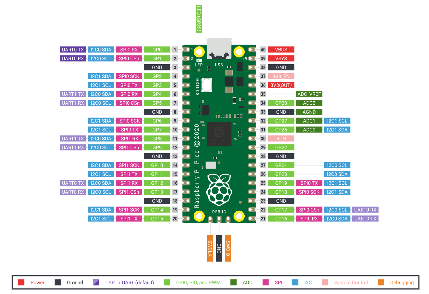
The default pins for the Pico's I2C bus 0 are taken by the LCD display's SPI bus. The connections in the settings file use I2C bus 0 with GP4 (header pin 6) for data (SDA) and GP5 (header pin 7) for clock (SCL). If the default pin for controlling the heater level is not used the following combinations are available.
| SDA GP# (Pin #) | SCL GP# (Pin #) | I2C bus |
|---|---|---|
| 0 (1) | 1 (2) | 0 |
| 6 (9) | 7 (10) | 1 |
| 26 (31) | 27 (32) | 1 |
VIN on the BME280 should be connected to 3V3 out (header pin 36). GND should be connected to any of the free ground connections on the Pico.
If the BME280 is not connected, an error message will display on the LCD.

| GP# | Pin | Function |
|---|---|---|
| 2 | 4 | Joystick up |
| 3 | 5 | Joystick centre press |
| 8 | 11 | SPI DI1 data (high) command (low) |
| 9 | 12 | SPI CS1 chip select (low active) |
| 10 | 14 | SPI SCK1 clock input |
| 11 | 15 | SPI DO1 data input |
| 12 | 16 | Reset (low active) |
| 13 | 17 | Backlight |
| 15 | 20 | User key A |
| 16 | 21 | Joystick left |
| 17 | 22 | User key B |
| 18 | 24 | Joystick down |
| 20 | 25 | Joystick right |
| VSYS | 39 | 1.8 to 5.5V power supply |
The Raspberry Pi Foundation offer a tutorial on installing MicroPython on a Pico.
The files in the code folder should be copied to the Pico. This can be done using Thonny.
- If there are no menus at the top to the Thonny window, switch to regular mode using the hyperlink in the top-right of the window and restart Thonny.
- Select View | Files
- Right click on the files to transfer and select Upload to /.
Rename pico-pid.py to main.py for the program to run when the device is plugged in.
Settings are stored in JSON format in settings.json.
| Key | Meaning | Typical value |
|---|---|---|
displaysleep_s |
seconds without action before LCD backlight dims | 30 |
displayupdate_Hz |
number of times per second the controls are checked | 5 |
heaterfreq_Hz |
PWM frequency in Hz | 16384 |
heaterpin |
GPIO number controlling the heater output by PWM | 0 |
i2cbus |
I2C bus used to connect to BME280 | 0 |
Kd |
derivative gain parameter in parallel-form PID equation (=Kp Td) | 963413 |
Ki |
integral gain parameter in parallel-form PID equation (=Kp/Ti) | 629.4 |
Kp |
proportional gain parameter in parallel-form PID equation | 49248 |
lookback_points |
number of measurements points used in autotune to find peaks or troughs | 60 |
noiseband_C |
number of degrees Celsius overshoot before heater state changes in autotune | 0.5 |
outmax_tune |
maximum PWM output for heater control during tuning | 65535 |
outmax |
maximum PWM output for heater control | 65535 |
outmin_tune |
minimum PWM output for heater control during tuning | 0 |
outmin |
minimum PWM output for heater control | 0 |
pressureoffset_hPa |
number of hPa to add to reading from BME280 | 0.0 |
rhoffset_pct |
number of percentage points to add to reading from BME280 | 0.0 |
sampletime_s |
seconds between BME280 measurements | 1.0 |
scl_pin |
I2C clock GPIO | 5 |
sda_pin |
I2C data GPIO | 4 |
setpoint_C |
setpoint temperature in °C | 37.0 |
smoothingalpha |
Exponential smoothing factor 0 < α ≤ 1 | 0.7 |
tempbar_frac |
fraction of screen width where vertical setpoint bar appears on temperature line | 0.6 |
tempoffset_C |
number of degrees to add on to reading from BME280 | 0.0 |
tuningrule |
set of empirical parameters to convert amplitude and period of tuning into PID gain parameters | "ziegler-nichols" |
Button A toggles whether the heater will turn on to reach the setpoint temperature. Run autotune before the first use.
Use the joystick to change the setpoint temperature. Pressing up or right raises the setpoint temperature, pressing down or left lowers it.

Button B engages the PID tuning routine. The heater will turn on (default is full power) until the setpoint is passed by a specified amount (default is 0.5 °C). When the temperature drops by a specified amount below the setpoint, the heater switches on again. The process is repeated until the period of oscillation and amount of gain can be calculated. These values are converted into the three PID parameters using the tuningrule setting (default is Ziegler-Nichols).
The amount of overshoot is set with noiseband_C. The minimum and maximum heater outputs for the bang–bang control are set with outmin_tune and outmax_tune.
Pressing button B again while tuning stops the tuning routine and the heater and preserves the original PID settings.

- LCD driver code adapted from Waveshare's model code
- Autotune and PID code adapted from t0mpr1c3's fork of an Arduino PID autotune library
- BME280 driver used without modification, based on original created by Kevin Townsend