-
Notifications
You must be signed in to change notification settings - Fork 6
1. Parts preassembly
Some of the parts need preassembly to be ready for the final assembly stage. In this chapter, we will combine electronics and 3D printed parts to create the building blocks for the robot. Before you start, be sure you have the correct electronic parts and the correct 3D printed parts. In every folder of the 3D printed parts, you can find photos of the electronic parts you need, also the code of every part can be founded in the Chapter 5 (Classes description) .
This is the only stage we will need some of the following tools:
- Side cutter
- Soldering iron
- A small Philips screwdriver
- A flat screwdriver
- Hot glue gun
- Superglue
Remove a small piece of plastic from the yellow motor using the side cutter.

Prepare two female to female jumper wires of different colors, take the side cutter and cut the one of two female socket, after carefully remove a small length of the plastic isolation and expose the copper from inside the wire.

Solder to the two motor terminals the wires.

Insert the motor inside the bottom part and pass the wires through the little slot of the top part.

Press the bottom part against the top part until secure.

Connect three female to female jumper wires to the sensor and write down the wire color to pin connection e.g. "RED -> 5V , BLACK -> Ground, GREEN -> Signal".

Slide the sensor inside the bottom of the 3D printed part in the special slots.

Slide the sensor disk on the shaft and place it in the special slots inside the bottom part.


Pass the wires through the little slot of the bottom part.

Press the bottom part against the top part until secure.
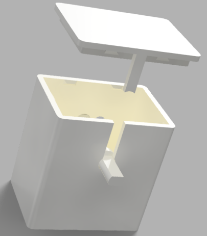
Connect three female to female jumper wires to the sensor and write down the wire color to pin connection e.g. "RED -> 5V , BLACK -> Ground, GREEN -> Signal".

Slide the sensor inside the bottom of the 3D printed part in the special slots.

Slide the sensor disk on the shaft and place it in the special slots inside the bottom part.


Connect the shaft coupler to the shaft. Later you can connect the odometer with the motor shaft using the coupler.

Connect three female to female jumper wires to the sensor and write down the wire color to pin connection e.g. "RED -> 5V , BLACK -> Ground, GREEN -> Signal/Digital".

Slide the sensor inside the bottom of the 3D printed part and gently pass the two Led through the holes. The blue part of the sensor should be the upside.

Pass the wires through the hole of the top part.

Press the bottom part against the top part until secure.
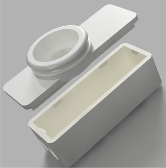
Slide the servo motor inside the of the 3D printed bottom part and pass the wires through the hole.
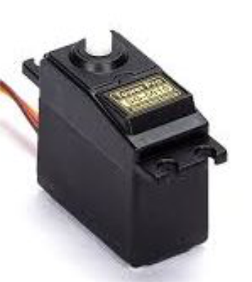

Press the bottom part against the top part until secure.

Connect four female to female jumper wires to the sensor and write down the wire color to pin connection e.g. "RED -> 5V , BLACK -> Ground, GREEN -> Echo, ORANGE -> Trigger".
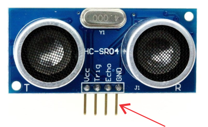
Slide the sensor inside the bottom of the 3D printed part.

Pass the wires through the hole of the top part.

Press the bottom part against the top part until secure.

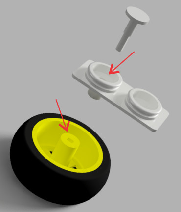
Pass the shaft through the hole of the large part and secure it with the wheel.
Connect the flexible cable on camera.


Slide the camera inside the bottom of the 3D printed part.

Pass the flexible cable through the hole of the top part.

Press the bottom part against the top part until secure.

Prepare two black, one red and one orange female to female jumper wires. Take the side cutter and cut the one of two female socket, after carefully remove a small length of the plastic isolation and expose the copper from inside the wire. The bottom side of the step-down circuit is labeled with the voltages. Unscrew the blue terminals and insert the orange wire to the terminal for the 9-36V and the red wire in the terminal for the 5V. Connect the black wires to the holes of the terminals with the "-" or Gnd label. Screw all the terminals and check if all the wires are secured.

Slide the circuit inside the bottom of the 3D printed part.

Press the bottom part against the top part until secure.
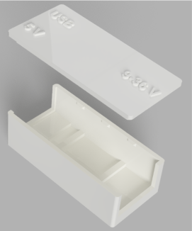
Insert the mini breadboard inside the 3D printed part.
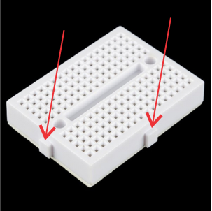
Press the bottom part against the top part until secure.

Press the Raspberry pi carefully against the base until all the board locked on the base.

Use the side cutter to cut 8 pins from the row.

Prepare one female to female jumper wire, take the side cutter and cut the one of two female socket, after carefully remove a small length of the plastic isolation and expose the copper from inside the wire.

Pass the end of the wire with the exposed copper from the small hole. Use the soldering iron and connect the wire to the first pin on the short side of 8 pin set. After connect the 7 remain pins with the first pin.
![]()
![]()
Finally press the 8 pin set in the slot until secured.
This is one of the most complex to wiring component, you should be careful with the voltages and the connection, an error here can damage the Raspberry PI.
Prepare seven female to female jumper wire, take the side cutter and cut the one of two female socket, after carefully remove a small length of the plastic isolation and expose the copper from inside the wire. Suggested one orange wire for 12V , one red wire for 5v, one black for ground and for the other four wire you are free to choose any color you want.

Remove from the board the two shortcut clip (green arrows). Unscrew the blue terminals and insert the orange wire to the terminal with 12V label, the red wire on the terminal with the 5V label, the black wire to the terminal with GND label and the other four cables to the remain terminals left and right . Screw all the terminals and check if all the wires are secured. Now connect 6 female to female jumper wires to the motor control pins (red arrows). The module is ready, please check again all the connections.

Press the motor driver carefully against the base until all the board locked on the base.

Before insert the batteries check the connections multiple times. That part requires three 18650 batteries. The circuit can charge the batteries with 12.3 V input and have 12V output . Also for the first time and every time you remove the batteries needs 12V input to activate the circuit.

If you want to place the battery module outside the robot you should print the battery block.
Insert the battery module into the bottom part with the batteries cells face down and pass the charging wires through the little slot (red arrow).

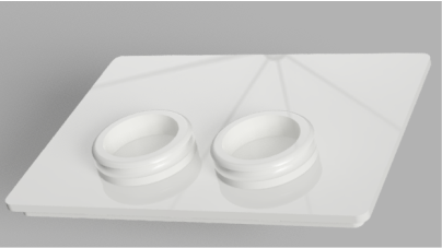
Press the the top part against the bottom part and the battery block is ready.
Glue the small black circular hat in the slot of the arm extender. To attach the extender to the servo use the small screw.
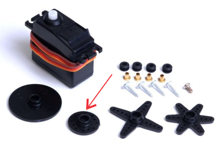

Glue the small black circular hat in the slot of the rotation base . To attach the base to the servo use the small screw.

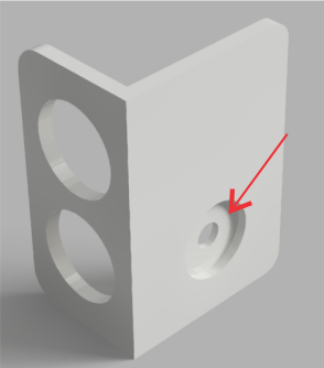
First you should glue the small hat to the small circular hat.
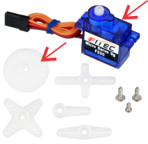
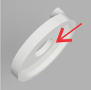
Next screw the to the servo motor and insert it to the slot in the base.

The cable of the servo motor should pass through the small hole in the side of the base.
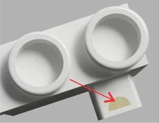
Next insert the other parts to the base with the follow order.

Finally press the top part against the base until everything is secured.
