
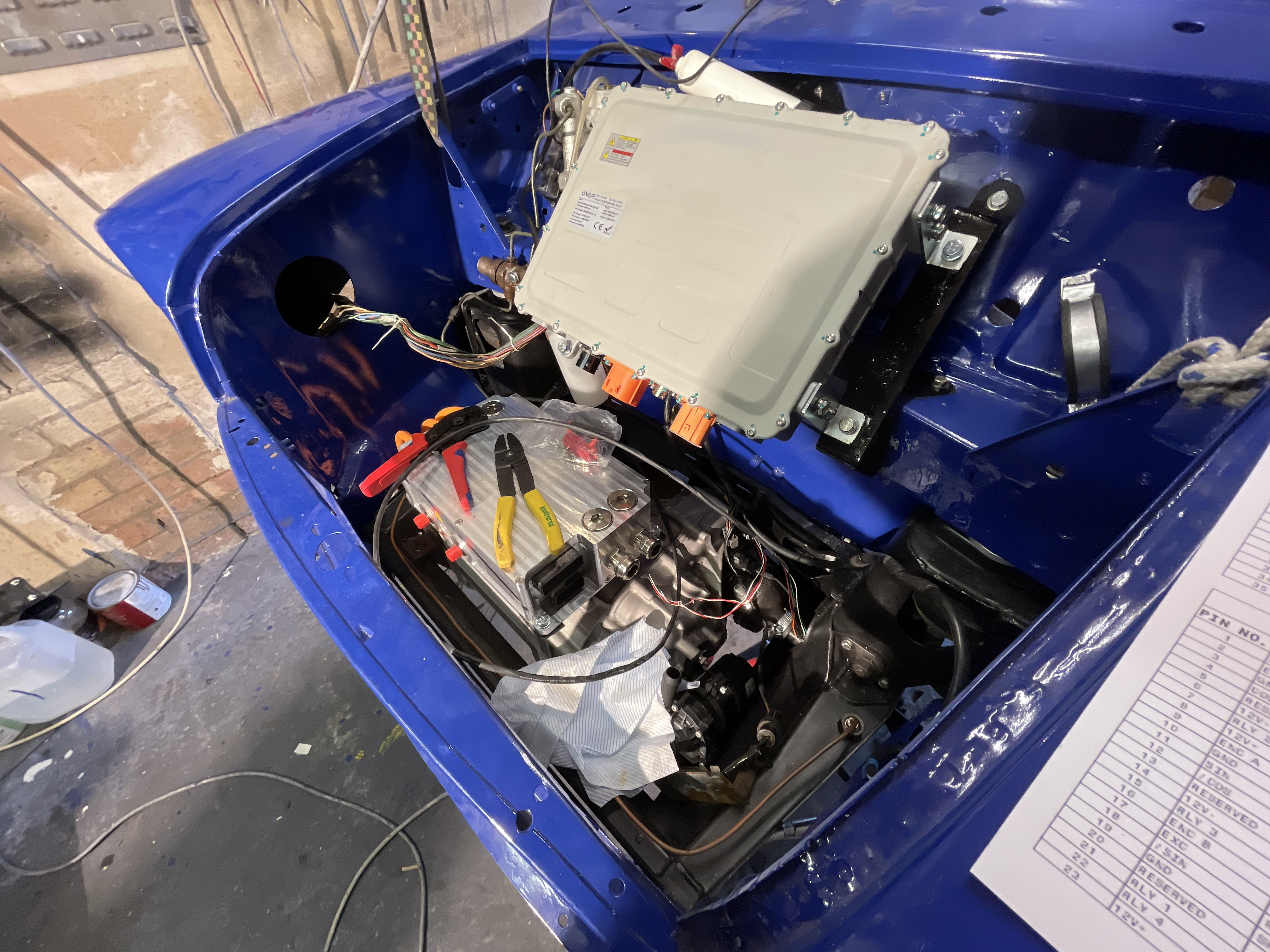
This repository documents the integration of the Cascadia Motion / Rinehart Motion Systems PM100 AC motor inverter into the BlueBoy EV powertrain project.
The primary reference is PM100_Reference_Guide.md, covering:
| Topic | Section |
|---|---|
| System overview and powertrain architecture | §1 System Architecture Overview |
| HV DC and 12V logic power connections | §2 Power Connections |
| J1 35-pin AMPSEAL connector pinout | §3 J1 Connector |
| J2 23-pin AMPSEAL connector pinout | §4 J2 Connector |
| Analog/digital I/O electrical specs | §5 I/O Electrical Details |
| RS-232 wiring, baud rate, and serial testing | §6 RS-232 Serial Interface |
| CAN A/B bus wiring and termination | §7 CAN Bus Interface |
| CAN byte-level message specs (0x0A0–0x0B0, 0x0C0–0x0C2) | Appendix C.4 Broadcast Message Byte Definitions |
| Command message 0x0C0 torque/speed/enable | Appendix C.5 Command Message |
| Parameter read/write messages 0x0C1 / 0x0C2 | Appendix C.6 Parameter Messages |
| EEPROM parameter address table | Appendix C.8 Key EEPROM Parameters |
| RMS GUI diagnostics software | §8 RMS GUI Software |
| C2Prog firmware flashing procedure | §9 C2Prog Firmware Flashing |
| Enable/disable and fault state machine | §10 Vehicle State Machine |
| Regenerative braking energy path | §11 Regenerative Braking |
| EEPROM configuration parameters | §12 Key Configuration Parameters |
| Terminology and abbreviations | §13 Glossary |
| Source documents and firmware version notes | §14 References |
- New to the system? Start with §1 System Architecture Overview.
- Wiring the J1 connector? See §3 J1 Connector and §6 RS-232 Serial Interface.
- Flashing firmware? See §9 C2Prog Firmware Flashing.
- Running diagnostics? See §8 RMS GUI Software.
Official Cascadia Motion documentation and software downloads: https://www.cascadiamotion.com/documentation