Home
Disclaimer
None of the authors, nor the Lancaster University Materials Science Institute, nor any contributor to the Ambuild program or its derivatives guarantee that the software and associated documentation is free from error. Neither do they accept responsibility for any loss or damage that results from its use. The responsibility for ensuring that the software is fit for purpose lies entirely with the user.
Acknowledgements
Table of Contents
| Page | ||
|---|---|---|
| Disclaimer | 1 | |
| Acknowledgements | 2 | |
| List of Figures | 4 | |
| 1.1 | About Ambuild | 5 |
| 1.2 | Concepts | 6 |
| 2.1 | Specifying Fragments and endGroups | 6 |
| 2.2 | Potential Parameters | 9 |
| 2.3 | The Input File | 9 |
| 3.1 | Setting Up the Cell | 10 |
| 3.2 | Creating a Cell Library | 10 |
| 3.3 | Specifying Bonding Rules | 11 |
| 4.1 | Creating a Linear Polymer | 12 |
| 4.2 | Filling the Cell with Building Blocks | 13 |
| 5.1 | Growing Blocks | 13 |
| 5.2 | Joining Blocks | 14 |
| 5.3 | Zipping Blocks | 15 |
| 6 | Deleting Blocks | 16 |
| 7.1 | Geometry Optimisation | 17 |
| 7.2 | Molecular Dynamics | 17 |
| 7.3 | Geometry Optimisation and Molecular Dynamics Combined | 18 |
| 8 | Running the Ambuild Code | 18 |
| 9 | Saving Results and Extracting Coordinates | 19 |
| 10 | Glossary | 20 |
| 11 | Example Input Scripts | 26 |
| 11.1 | Example growBlocks Script | 26 |
| 11.2 | Example joinBlocks Script | 27 |
| 11.3 | Example zipBlocks Script | 28 |
| 11.4 | Example Artificial Synthesis Procedure | 29 |
| 11.5 | Example Statistical Sampling Script | 32 |
Author’s note: Throughout this manual named variables and parameters will be denoted using typewriter text to enable differentiation from the main body of text. Hyperlinks to external webpages will be underlined. Please note the capitalisation of the variables shown below is intentional and should be maintained throughout.
List of Figures
| Figure | Figure Caption | Page |
|---|---|---|
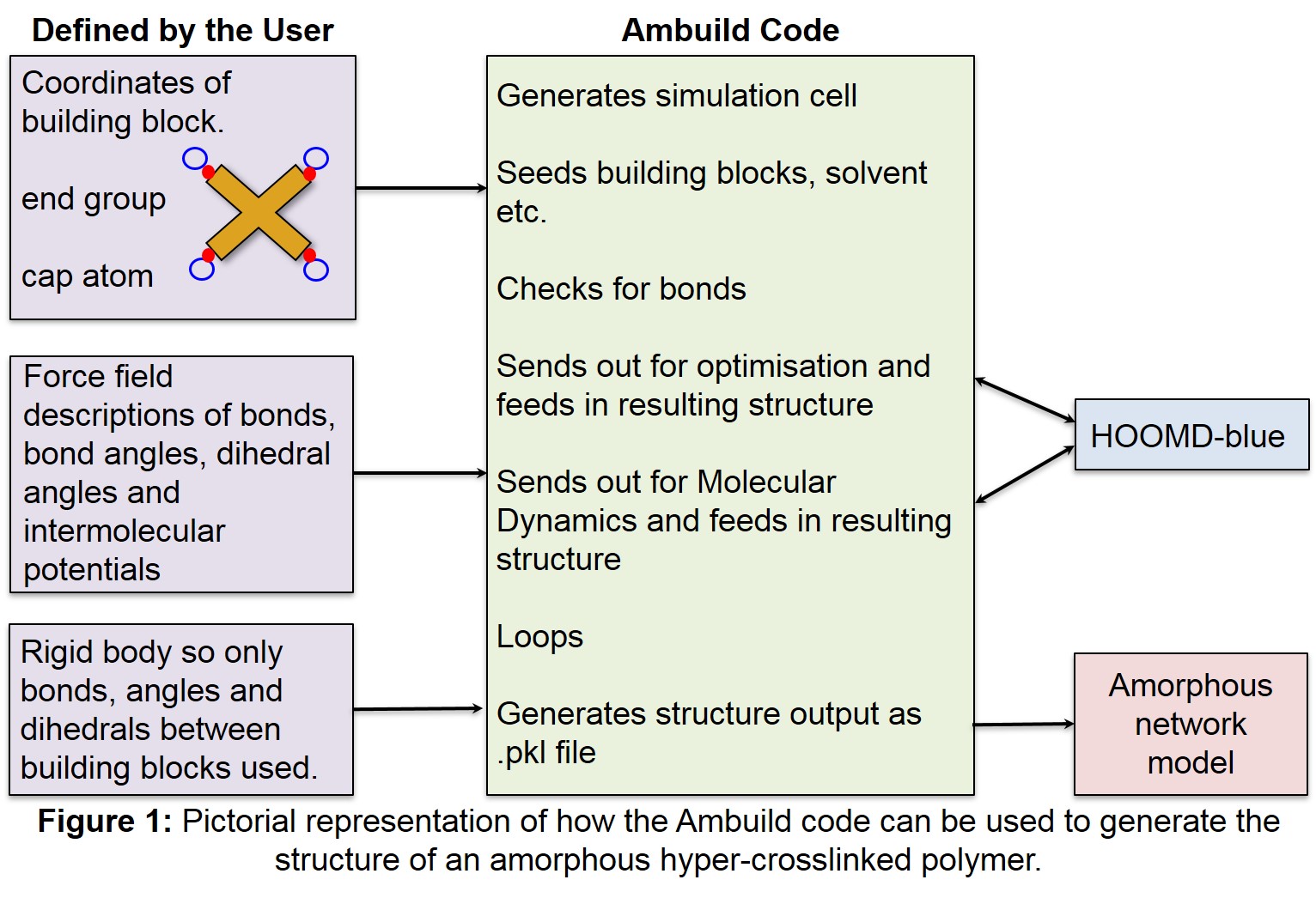
| 1 | Pictorial representation of how the Ambuild code can be used to generate the structure of an amorphous hyper-crosslinked polymer. | 5 |
| 2 | The Ambuild code is written in Python and integrates to the HOOMD-blue molecular dynamics code. | 6 |
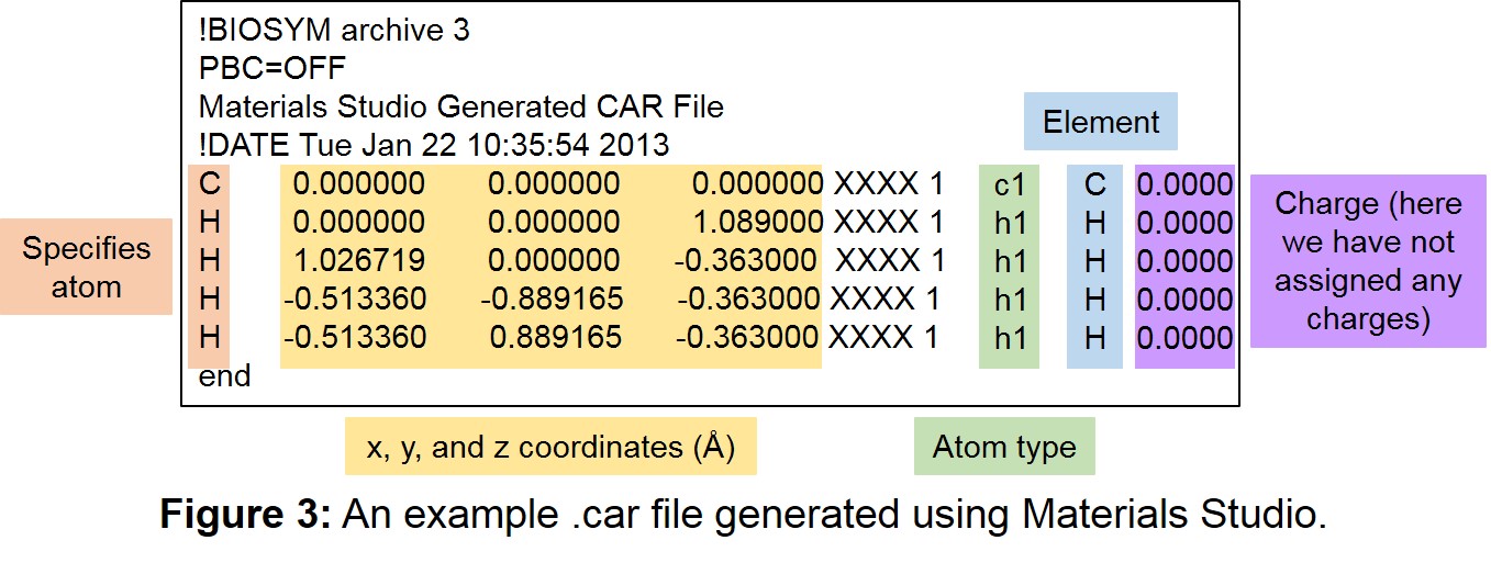
| 3 | An example .car file generated using Materials Studio. | 7 |
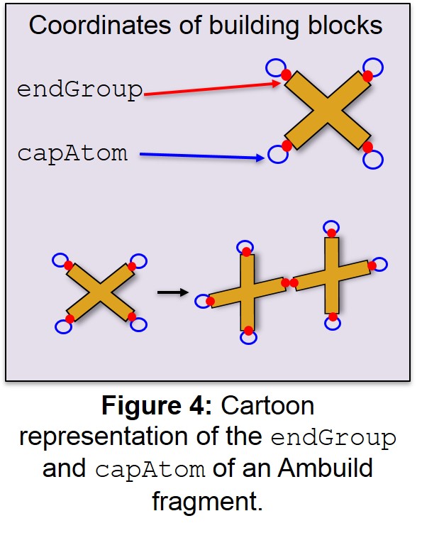
| 4 | Cartoon representation of the endGroup and capAtom of an Ambuild fragment. | 8 |
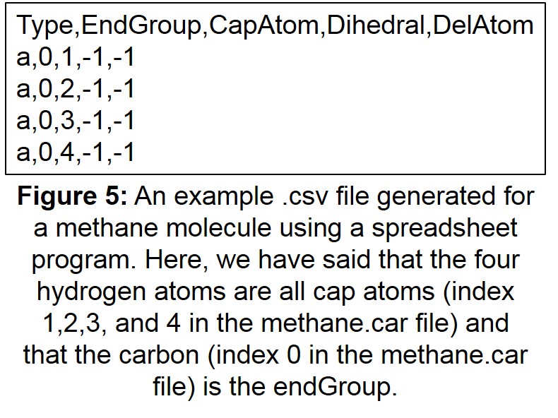
| 5 | An example .csv file generated for a methane molecule using a spreadsheet program. | 9 |
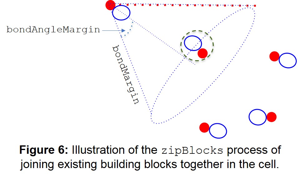
| 6 | Illustration of the zipBlocks process of joining existing building blocks together in the cell. | 15 |
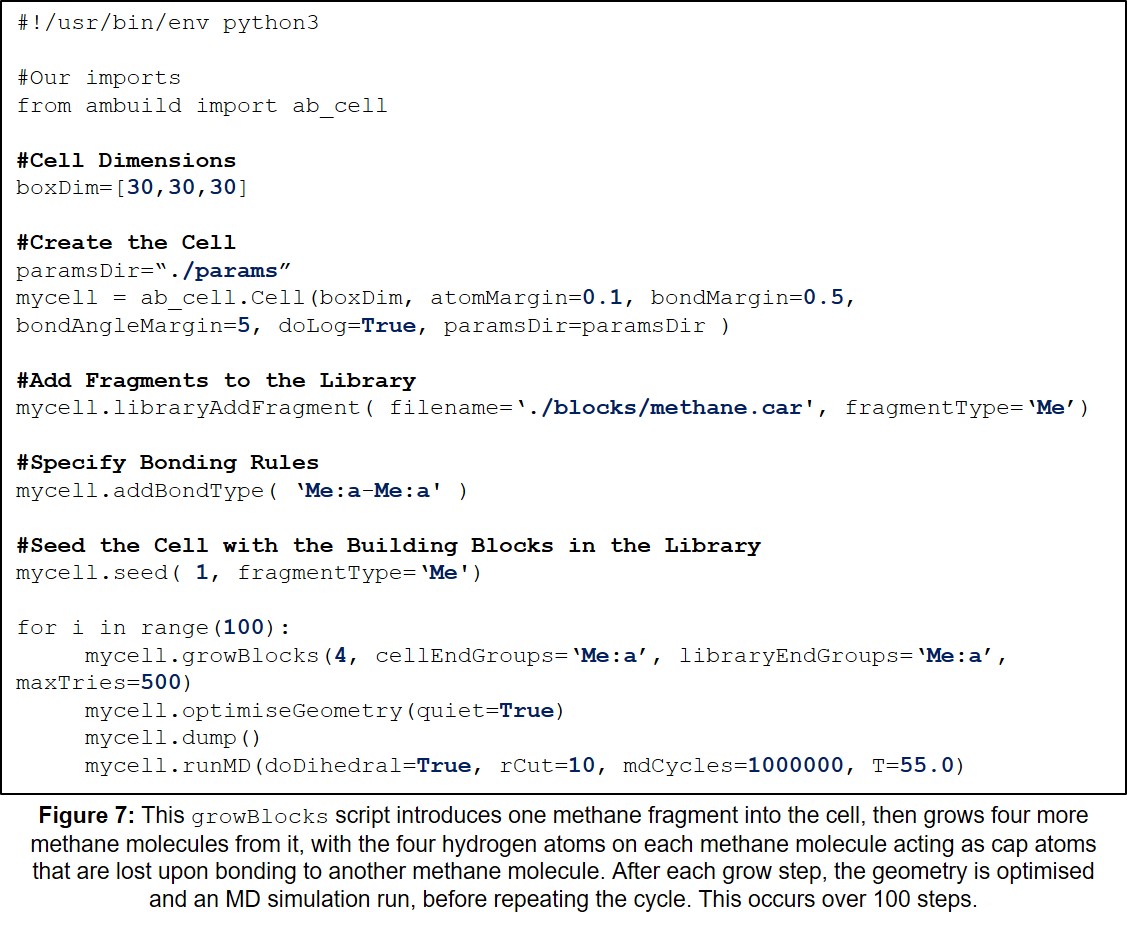
| 7 | Example growBlocks Input Script. | 27 |
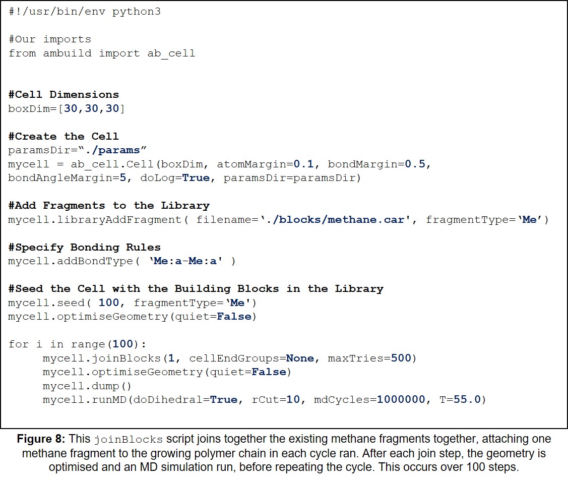
| 8 | Example joinBlocks Input Script. | 28 |
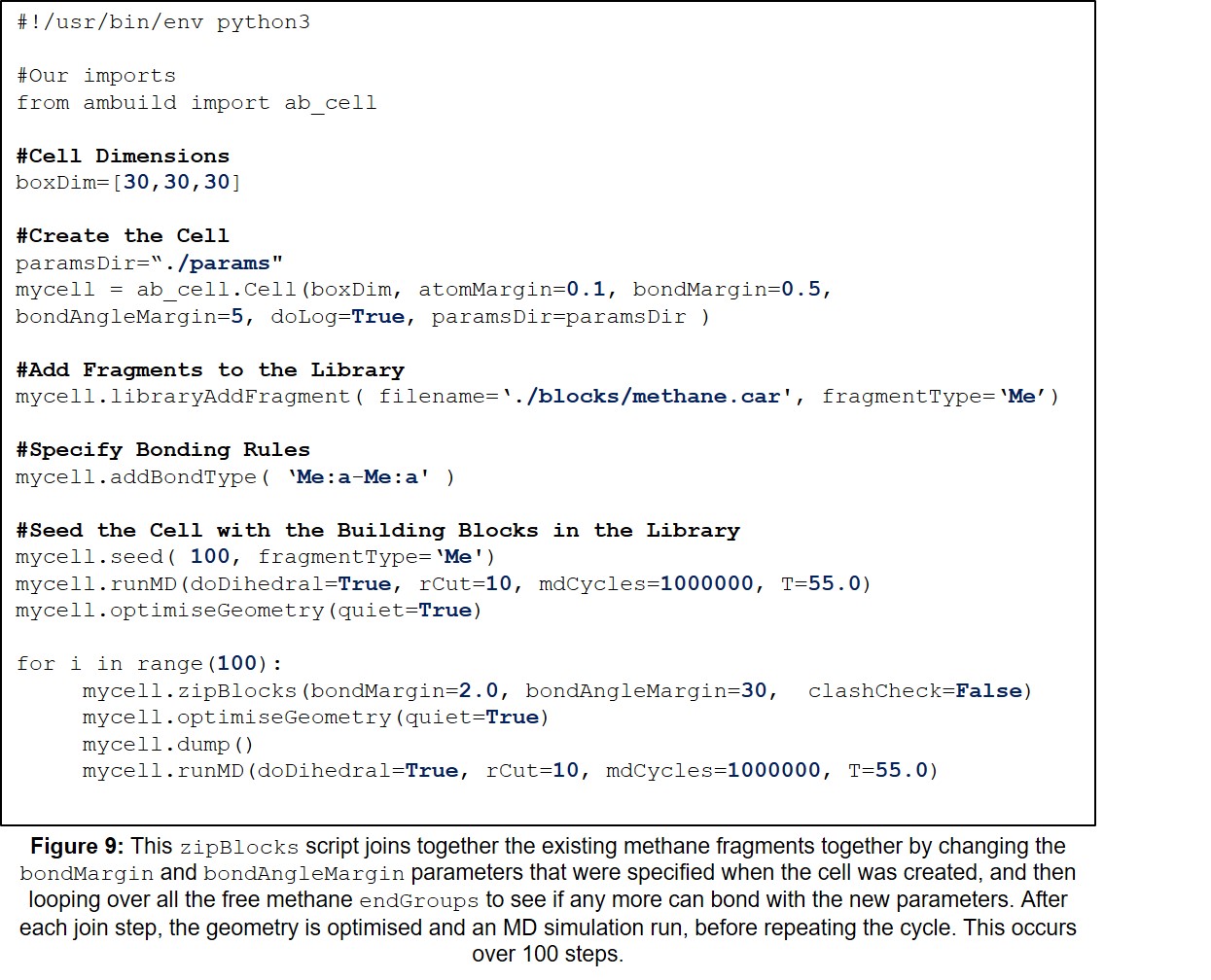
| 9 | Example zipBlocks Input Script. | 29 |
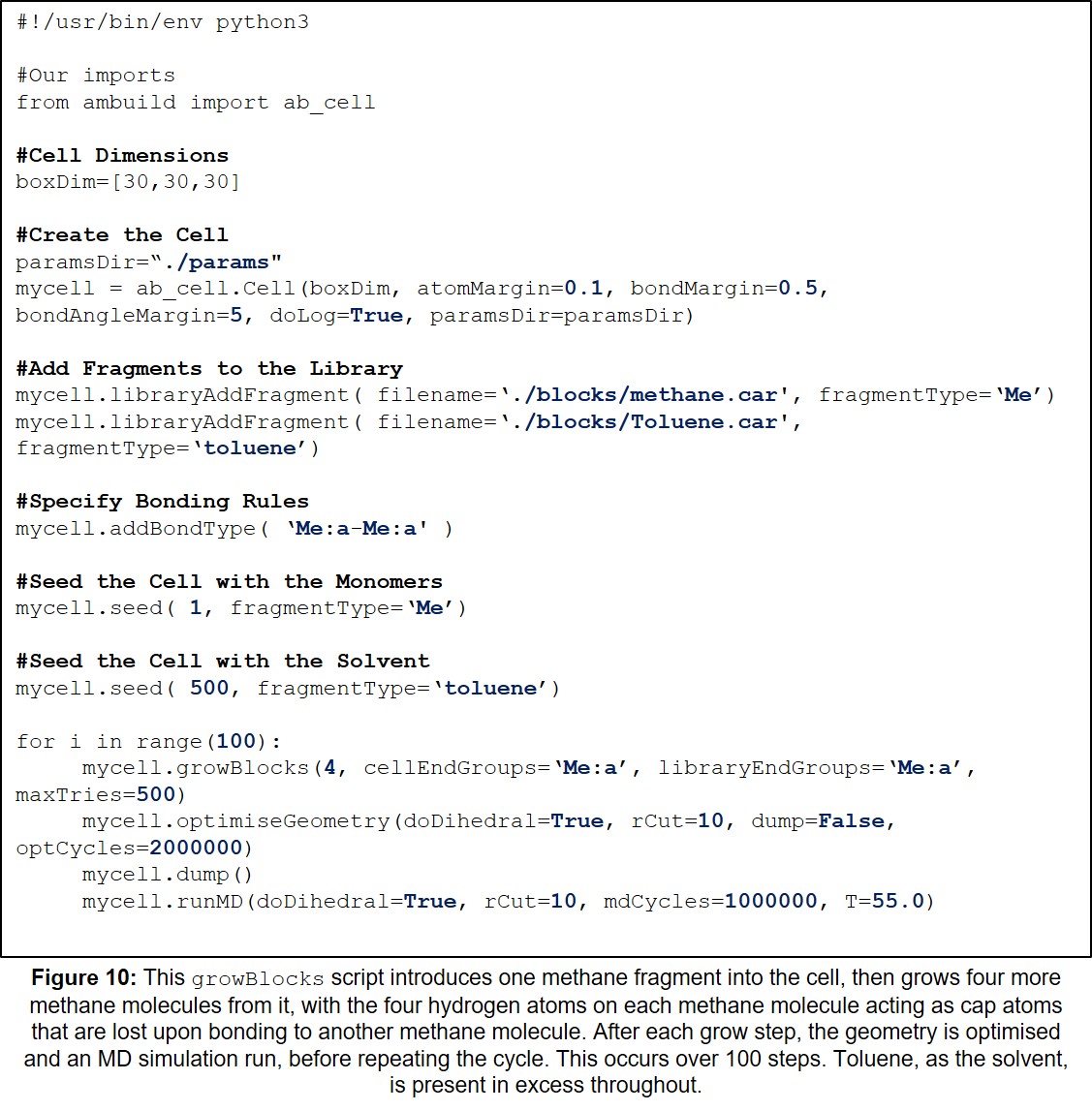
| 10 | Example growBlocks Input Script with Solvent. | 30 |
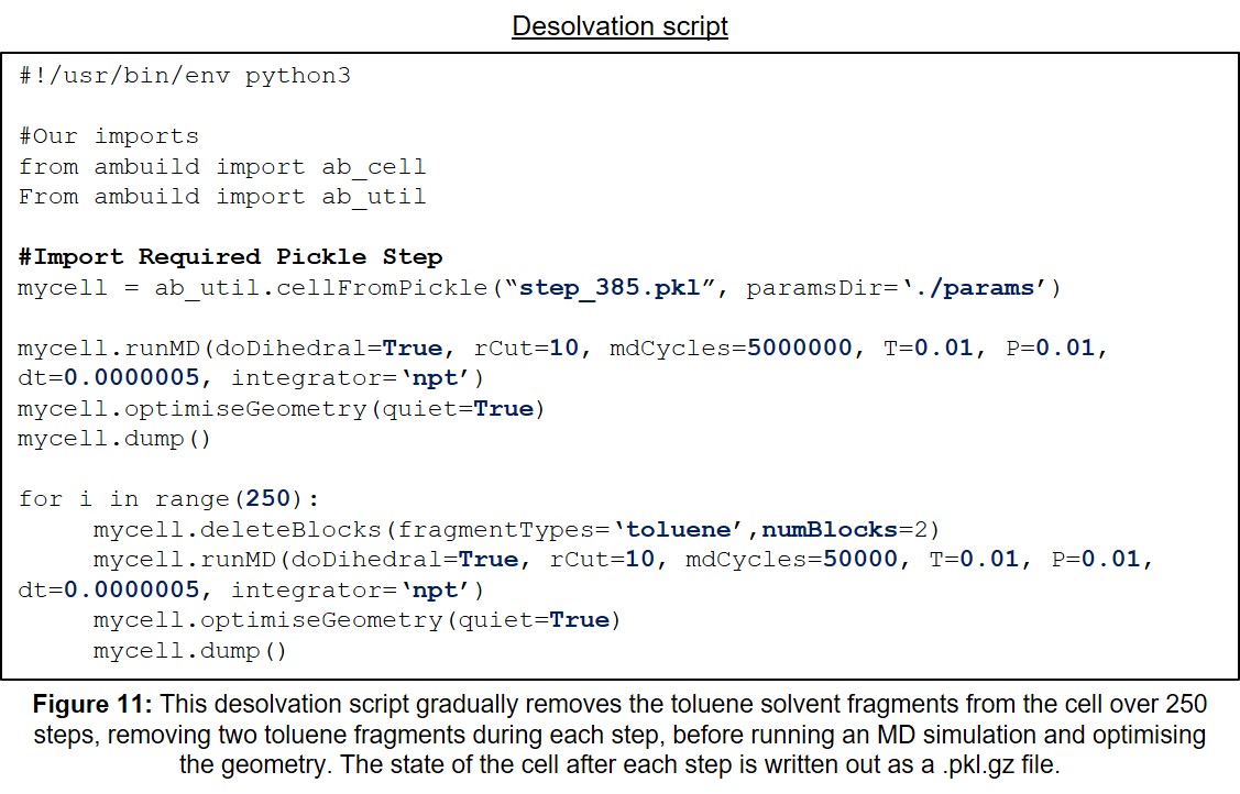
| 11 | Example Desolvation Input Script. | 31 |
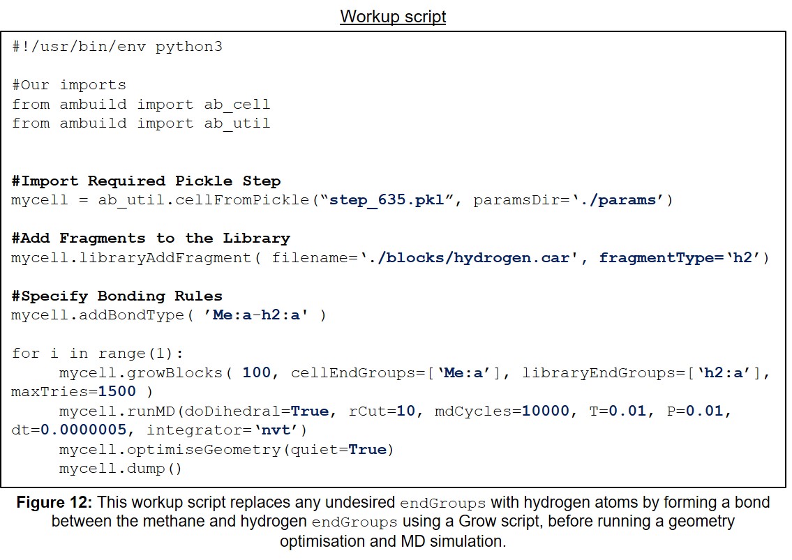
| 12 | Example Workup Input Script. | 32 |
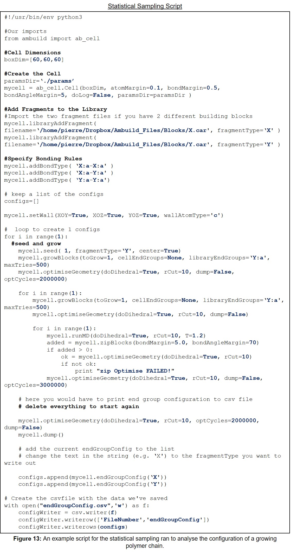
| 13 | An example script for the statistical sampling ran to analyse the configuration of a growing polymer chain. | 33 |
1.1 About Ambuild
The Amorphous Builder (Ambuild) code is a program designed to simulate the conditions under which amorphous hyper-crosslinked polymers are formed, building the polymer network up from the molecular building blocks themselves (Figure 1).
Ambuild is written in Python and integrates to HOOMD-blue (Figure 2), a Graphics Processing Unit (GPU) -based molecular dynamics (MD) code also written in Python. (HOOMD-blue can be accessed via: http://codeblue.umich.edu/hoomd-blue). The integration of the Ambuild code with HOOMD-blue enables very large simulation cell sizes to be used, whilst retaining precise control of the simulation cell contents and structure generation process.
1.2 Concepts
Ambuild works with cells, fragments, building blocks, and endGroups:
- The cell is a volume of space that will be filled with molecular
building blocks.
- Fragments are molecules that may contain one or more endGroups that
can be used to form bonds. Fragments are always contained within building blocks.
- A building block may house one or more fragments of the same or
different types. The fragments within a building block are bonded to each other via their endGroups, the atoms which will form part of the new bond between building blocks. Rules can be specified for which endGroups can bond to which others, the dihedral angle around the bond that the fragment should adopt, and any atoms that may need to be removed on bonding, such as occurs during an unsaturation process.
2.1 Specifying Fragments and endGroups
The molecular fragments are specified using two input files:
- A “.car” file, which contains the coordinates and atom types of each
of the polymer building blocks (each building block having a separate .car file). This file can be prepared using programs such as Avogadro or Materials Studio, and more information about the format of this file can be found at: http://chem5.nchc.org.tw/software/document2007/insightII/doc/formats980/File_Formats_1998.html#781840). An example .car file is given in Figure 3.
- A “.csv” file that defines which atoms are endGroups and capAtoms
etc. The .csv file should have the same prefix as the .car file, but with a .csv suffix instead of .car. This is a standard comma-separated file that can be created and edited with any spreadsheet program.
The first line of the .csv file is a header naming the columns (case isn’t important here, but the field names must be correct):
Type,endGroup,capAtom,dihedral,delAtom
Each subsequent line defines an endGroup, with each column separated by a comma. The first three columns (Type, endGroup, and capAtom) are required, whilst the other two (dihedral and delAtom) are optional. The indices in the file start from 0, meaning that the first atom has an index of 0, the second 1, the third 2 etc.
The meanings of the columns given in the .csv file are as follows:
- Type: This is a string (starting with a letter) that names the
endGroup. This is used to specify bonding rules and to control which endGroups in which building blocks are bonded in Grow or Join steps (see sections 5.1 and 5.2).
- endGroup: This is the index of the atom in the .car file that is to be
the endGroup (the atoms that form part of the new bond between fragments) (Figure 4). As with the .csv file, the indexing in the car file starts from 0, so if the first atom in the .car file is to be the endGroup, the endGroup column should be 0.
- capAtom: This is the index of the atom in the .car file that is to be
the capAtom (the atom that caps the endGroup and defines the vector that the new bond will be made along) (Figure 4). The capAtom is removed when the new bond is formed and the corresponding endGroup in the other building block may not be in the same position, depending on the type of the two endGroups, which defines the new bond length.
- dihedral: This optional column specifies the atom that defines the
dihedral angle around the bond between two endGroups. This can be used to specify the orientation of molecules when they are attached with a Grow step. If the dihedral argument is given as “ -1 ”, or omitted, this means that there is no dihedral angle.
- delAtom: This optional column specifies an atom that will be removed
when the endGroup forms a bond. This can be used to unsaturate an atom on bonding, for example, if the endGroup is the nitrogen of an NH2 group, one of the hydrogen atoms could act as the capAtom and the other as the delAtom. On bonding to another NH2 endGroup a N=N double bond would be formed. If the delAtom argument is given as “ -1 ”, or omitted, this means that no atoms should be deleted during bond formation.
An example .csv file is given in Figure 5.
2.2 Potential Parameters
It is necessary to supply Ambuild with any potential parameters for bonds, bond angles, dihedral angles, and intermolecular potentials required in any HOOMD-blue MD simulation or structural optimisation. These are defined in a set of .csv files: bond_params.csv, angle_params.csv, dihedral_params.csv, improper_params.csv, and pair_params.csv.
The Ambuild code uses a simple harmonic bond and angle potential, a cosine harmonic dihedral and improper potential and a Lennard-Jones pair potential. The building blocks are held rigid, meaning that only the bonds, bond angles and dihedral angles between building blocks are described. (More information can be found at: http://glotzerlab.engin.umich.edu/hoomd-blue/).
2.3 The Input File
The Input file is the top level Python script, containing all the information about where the building blocks and parameters are located, as well as any bonding rules specified. This is saved as a “.py” script. The Input file specifies how Ambuild should assemble the amorphous hyper-crosslinked polymer. This runs in the same way as a normal Python script, with the option to write the output to a log file. Structural output is given as a Python “pickle” file (.pkl, a serialised representation of the entire cell object), which may be converted to a .cml or .xyz file so it may be viewed using programs such as Avogadro2. The .cml file displays the periodic boundaries of the unit cell, but any bonds that extend across the periodic boundary will be omitted, meaning that this file should not be used for extracting structural data, it is simply for visualisation. The .xyz file simply gives all of the x, y, and z coordinates.
3.1 Setting Up the Cell
Ambuild creates its structures in a cubic cell. The first step is to create an empty cell object. This is done using the following command:
boxDim=[20,20,20]
mycell = cell.Cell( boxDim, atomMargin=0.5, bondMargin=0.5, bondAngleMargin=15, doLog=False )
This creates an empty cell object called ‘mycell’. The name mycell is used to prevent this clashing with ‘cell’, the name used to import the Cell code module.
The variables in the boxDim and cell arguments are given as:
- boxDim: This is a list of three numbers specifying the size of the
cell A, B, and C dimensions (given in angstroms, Å). Dimensions are defined from 0 to A, B, or C.
- atomMargin: The additional distance to be added on to the van der
Waals radii of two atoms to determine if they are close enough to clash.
- bondMargin: Two atoms are considered close enough to bond if they are
within the bond length defined for the two atoms +/- the bondMargin.
- bondAngleMargin: The tolerance (in degrees) from the ideal of 180 that
defines an acceptable bond.
- doLog: This argument (expressed as True or False) specifies if a log
file will be created. This is not recommended as it generates lots of data and slows the program.
Alternatively, the cell can be read from a .car file using the filePath argument instead of the boxDim argument. The filePath argument gives the location of the .car file containing the cell dimensions and the coordinates of molecules. In this case the molecule will be read in as a static structure that is not moved during any of the MD or geometry optimisation steps. The name of this static will be named after the .car file. When using the filePath argument, the cell dimensions will be taken from the PBC line in the .car file, e.g.:
PBC 40.0000 30.0000 30.0000 90.0000 90.0000 90.0000 (P1)
3.2 Creating a Cell Library
With the cell defined, it is possible to begin specifying which fragments go into the cell. This is done by creating a cell library that contains all the building blocks that will be used in the simulation, using the following command:
mycell.libraryAddFragment( filename=fragA, fragmentType='A' )
The variables in the libraryAddFragment argument are:
- filename: the path to the .car file. There will need to be a
corresponding .csv file that defines the endGroups and capAtoms etc.
- fragmentType: a name that will be used to identify the fragment. This
cannot contain the ":" or "-" characters.
- Solvent: This optional variable can be used to specify that this
fragmentType is solvent and so won't be clash-checked in Zip steps.
As many fragments can be added as desired. The only requirement is that each fragment is named differently.
3.3 Specifying Bonding Rules
With the fragments added, bonding rules can be specified using the following command:
mycell.addBondType( 'A:a-B:a' )
endGroups are defined by the fragmentType they belong to (which is set by the fragmentType argument to libraryAddFragment), along with the identifier for that endGroup which is specified in the first column of the .csv file. These are separated by a colon (“:”), so an endGroup is expressed in the form:
fragmentTypeX:endGroup**x**
A bond is specified by two endGroups, separated using a hyphen, giving a bond identifier the form of:
fragmentType1:endGroup**1**-fragmentType**2**:endGroup**2**
In the above example, a bond was formed between endGroup ‘a’ of fragmentType ‘A’ and endGroup ‘a’ of fragmentType ‘B’.
Building blocks can have multiple endGroups, depending on the nature of the building block, and so it is possible to form multiple bonds between two fragmentTypes.
Sometimes it is necessary to limit the number of bonds of a particular type to an individual fragment. For example, if a fragment has three nitrogen endGroups, but only one can be used before the others become unavailable for bonding. This is achieved with the setMaxBonds argument below:
mycell.addBondType( bondType='A:a-B:a', count=1 )
The arguments in the setMaxBonds argument are as follows:
- bondType: The bondType as was specified when using the addBondType
argument above.
- count: The maximum number of permissible bonds for a single fragment.
4.1 Creating a Linear Polymer
To create a linear polymer, the following line can be used:
growPolymer(monomers=['A','B'], ratio=[1,1], length=10, random=False, center=False)
This is the simplest and most automatic way to create a structure. The variables used in the growPolymer argument are given below:
- monomers: The list of Ambuild fragmentTypes (as specified when adding
each fragment to the cell using the libraryAddFragment argument-see Section 3.2) that will be joined to create a subunit.
- ratio: A list of integers specifying the number of each type in the
subunit. This list should be as long as the list of monomers.
- length: The number of subunits that will be created.
- random: Whether to build up the polymer deterministically or
stochastically, but where the final ratio of fragments will approach that specified in ratio. Expressed as True or False.
- center: True or False argument asking whether to place the first
monomer in the centre of the cell or not (if possible).
The fragment and ratio lists define the construction of the subunit. E.g.:
monomers = ['A', 'B']
ratio = [1,2]
gives: [ABB]
Another example would be:
monomers = ['A', 'B', 'A', 'B']
ratio = [1,2,3,1]
gives: [ABBAAAB]
4.2 Filling the Cell with Building Blocks
The seed command is used to seed the system with molecular building blocks:
seed(100, fragmentType='A', maxTries=500, center=False )
The arguments to seed a cell are:
- nblocks: The number of building blocks of that fragmentType to add to
the cell.
- fragmentType: The type of fragments to add. If the fragmentType is
given as ‘None’, or omitted, then fragments will be randomly chosen from the library.
- maxTries: The maximum number of attempts to make when adding a
building block before the seed step fails and returns.
- center: Expressed as True or False, this argument asks whether or not
to place the first block in the centre of the cell (if possible).
- point: A list of three floats defining a point around which the
centroids of the blocks will be seeded (requires the radius argument).
- radius: A single float specifying the radius of a sphere around the
point within which the centroids of the building blocks will be seeded (requires the point argument).
- zone: A list of six floats specifying a box within the cell within
which the centroids of the blocks will be seeded. The coordinates are given in the form of: x, x, y, y, z, z, rather than xyz, xyz.
Once the system is seeded, Grow or Join steps are used to either add new blocks to the system, or join existing blocks together, respectively.
5.1 Growing Blocks
Growing a building block involves adding a fragment to an existing block in the cell. This is done with the growBlocks command:
mycell.growBlocks( 10, cellEndGroups=['A:a'], libraryEndGroups=['B:a'], dihedral=90, maxTries=500 )
The arguments to the growBlocks argument are as follows:
- toGrow: Specifies the number of blocks to add.
- cellEndGroups: A list of the endGroup types in the cell that the new
blocks will be bonded to. If more than one endGroup type is supplied, the endGroup will be randomly chosen from that list.
- libraryEndGroups: A list of the endGroup types from the library that
will be used to form the bonds. If more than one endGroup type is supplied, the endGroup will be randomly chosen from that list.
- dihedral: The dihedral angle about the bond (given in the third column
in the .csv file).
- maxTries: The maximum number of attempts to make before giving up on
growing the block.
5.2 Joining Blocks
The joinBlocks command is used to join existing blocks in the cell together:
mycell.joinBlocks( 10, cellEndGroups=['A:a','B:a'], dihedral=90, maxTries=500 )
This will randomly select two blocks (with endGroups specified in the list supplied to cellEndGroups, or just two random blocks if cellEndGroups is expressed as ‘None’) and attempt to bond them by removing the second block from the cell and attaching it to the first. If the bond fails (for example, due to clashes), the second block will be returned to its original position.
The arguments required for the joinBlocks command are:
- toJoin: The number of blocks to join.
- cellEndGroups: A list of the different endGroup types that should be
bonded. If this is expressed as ‘None’, endGroups will be chosen at random.
- dihedral: The dihedral angle about the bond (given in the third column
in the .csv file).
- maxTries: The maximum number of moves to try when joining two blocks.
5.3 Zipping Blocks
The zipBlocks command joins existing building blocks in the cell by changing the bondMargin and bondAngleMargin parameters that were specified when the cell was created, and then looping over all the free endGroups to see if any more can bond with the new parameters (Figure 6). The blocks remain stationary in this step, unlike in the joinBlocks argument.
The zipBlocks command is expressed as:
zipBlocks(bondMargin=5, bondAngleMargin=30, clashTest=True, clashDist=1.6)
The zipBlocks argument looks for capAtoms that are within a cone constructed from the bond vector between the endGroup and capAtom. In the case of the example above, the cone will be of length 5 Å and angle 30°.
The variables in the zipBlocks argument are:
- bondMargin: The new bond margin, given in angstroms.
- bondAngleMargin: The new bond angle margin, given in degrees.
- clashCheck: This is a True or False check for clashes between the bond
and any atoms that fall within a cylinder of radius clashDist (default = 1.6 Å), centred on the bond axis.
- clashDist: A float specifying the perpendicular distance from the bond
axis that determines if an atom is clashing with the bond. clashDist must be smaller than the cell size to ensure that the atom is visible.
- selfBond: This is a True or False check that asks whether or not a
block should be allowed to bond to itself, with a default of True.
The essential arguments to zipBlocks are bondMargin and bondAngleMargin. The remaining variables are optional to this command.
If the bonds appear “stretched” in the resulting polymer, the zip distance should be reduced. This will prevent bonds forming between endGroups that are too far apart for the bond to be realistic.
Once the cell has been filled with blocks, it is possible to either optimise the geometry of the cell contents or run a molecular dynamics simulation.
6 Deleting Blocks
Blocks can be removed from the cell with two commands:
- deleteBlocksIndices. The variables for this argument are:
- indices: A list of the indices of the blocks to be deleted.
- save: This saves all of the deleted blocks so they can be re-added
with the restoreBlocks command.
- deleteBlocksTypes: This deletes numBlocks of the specified fragment
type. The variables for this argument are:
- fragmentType: the fragmentType, or list of fragmentTypes of the blocks
to be removed.
- numBlocks: This optional variable specifies the number of blocks to
remove. If omitted all blocks of the specified fragmentTypes will be removed.
- multiple: If True, this will remove blocks that contain more than one
fragment, if False, this will only remove single-fragment blocks.
- save: This saves all of the deleted blocks so they can be re-added
with the restoreBlocks command.
7.1 Geometry Optimisation
Rigid body optimisation is carried out using the mode_minimize_rigid_fire optimiser. The optimiser is run with a command similar to the following:
mycell.optimiseGeometry( rigidBody=True, doDihedral=True, quiet=True, rCut=5.0, optCycles=1000000, dt=0.005, Etol=1e-5)
The arguments accepted by optimiseGeometry are:
- rigidBody: This asks whether to do a rigid-body (True) or all-atom
(False) optimisation.
- doDihedral: This asks whether or not to include the dihedral terms
(True or False).
- doImproper: This asks whether or not to include the improper terms
(True or False).
- rCut: This is the van der Waals cut-off distance used (angstroms).
- optCycles: This is the number of HOOMD-blue optimisation cycles to
run.
- quiet: This asks whether the normal HOOMD-blue runtime output should
be printed to the screen (False) or not (True).
All other arguments accepted by the mode_minimize_rigid_fire optimiser are passed through, so for example, parameters such as fdec, alpha_start, etc. can be set in the call to optimiseGeometry. (The arguments accepted by the mode_minimize_rigid_fire optimiser are given in the following location: https://lost-contact.mit.edu/afs//umich.edu/user/j/o/joaander/Public/hoomd-web/doc/classhoomd__script_1_1integrate_1_1mode__minimize__rigid__fire.html).
7.2 Molecular Dynamics
MD simulations are run using the nvt (fixed volume), nvt_rigid, npt (fixed pressure), or npt_rigid integrators within HOOMD-blue. More information about the MD integrators can be found at: https://hoomd-blue.readthedocs.io/en/stable/module-md-integrate.html).
MD simulations can be ran using:
mycell.runMD(doDihedral=True, quiet=False, rCut=5.0, mdCycles=100, T=1.0, tau=0.5, P=1.0, tauP=0.5, dt=0.0005, dump=True, dumpPeriod=20, integrator='npt')
The variables for the runMD argument are given as:
- doDihedral: This asks whether or not to include the dihedral terms
(True or False).
- quiet: This asks whether the normal HOOMD-blue runtime output should
be printed to the screen (False) or not (True).
- rCut: This is the van der Waals cut-off distance used (angstroms).
- mdCycles: This is the number of HOOMD-blue MD cycles to run.
- T: The temperature coefficient used in the simulation (this doesn’t
directly relate to a temperature in Kelvin and is reliant on a number of factors).
- P: The pressure coefficient used in the simulation.
- dump: A True or False command asking whether or not to save the
current state of the cell at various intervals.
- dumpPeriod: How often to save the current state of the cell (e.g. a
dumpPeriod of 20 indicates that the state of the cell should be saved after every 20 steps).
The integrator option can be either 'nvt', or 'npt', where 'nvt' runs by default.
7.3 Geometry Optimisation and Molecular Dynamics Combined
In order to save copying data between Ambuild and HOOMD-blue, a combined MD and optimisation command has been created. This runs a very short optimisation loop to stabilise the structure, then runs an MD simulation, before running a full geometry optimisation to convergence (if possible). An example command to do this is:
mycell.runMDAndOptimise( doDihedral=True )
All the arguments accepted by the optimiseGeometry and runMD commands are accepted by runMDAndOptimise.
8 Running the Ambuild Code
To run Ambuild the python script is simply run in the directory where the python input script is located using:
python methane.py
where in the example above, the name of the input script is methane.py.
This will output to the screen. To output to a log file (called log) the following command should be used:
python methane.py > log>&1
To run this script in the background, which is recommended as the terminal can still be used while the script is running, the command becomes:
nohup python methane.py > log>&1 &
9 Saving Results and Extracting Coordinates
By default, Ambuild does not save any data or coordinates. The dump command is used to save the current state of the cell at various intervals. This is done using:
mycell.dump()
The dump command creates a python .pkl file that will be named step_X.pkl where X is a number that will increment each time that the dump command is called.
In order to extract coordinates the util.py script in the builder directory (~/opt/ambuild/builder/util.py) can be used. The script should be called with the path to the .pkl file as the first argument, e.g.
~/opt/ambuild/builder/util.py step_X.pkl
The util script will then create a .xyz file of the coordinates and a .cml file suitable for viewing with Avogadro2. If necessary, the util.py.orig could be used as a suitable alternative to util.py.
The util script also accepts a “--fragments” or “-f” argument, which tells the script to write out files for each fragment separately. This is done as follows:
~/opt/ambuild/builder/util.py -f step_X.pkl
The util script also accepts a “--blocks” or “-b” argument, which tells the script to write out separate files for each block in the cell. This is done as follows:
~/opt/ambuild/builder/util.py -b step_X.pkl
10 Glossary
| Term | Explanation | Page(s) |
|---|---|---|
| addBondType | Specifies a bonding rule between two endGroups. | 11, 12 |
| atomMargin | The additional distance to be added on to the van der Waals radii of two atoms to determine if they are close enough to clash. | 10 |
| bondAngleMargin | The tolerance (in degrees) from the ideal of 180 that defines an acceptable bond. | 10, 15 |
| bondMargin | Two atoms are considered close enough to bond if they are within the bond length defined for the two atoms +/- the bondMargin. | 10, 15 |
| bondType | The bondType as was specified when using the addBondType argument. | 12 |
| boxDim | This is a list of three numbers specifying the size of the cell A, B, and C dimensions (given in angstroms, Å). Dimensions are defined from 0 to A, B, or C. | 10 |
| capAtom | This is the index of the atom in the .car file that is to be the capAtom (the atom that caps the endGroup and defines the vector that the new bond will be made along) (Figure 4). The capAtom is removed when the new bond is formed and the corresponding endGroup in the other building block may not be in the same position, depending on the type of the two endGroups, which defines the new bond length. | 7, 15 |
| cellEndGroups | A list of the endGroup types in the cell that the new blocks will be bonded to. If more than one endGroup type is supplied, the endGroup will be randomly chosen from that list. If this is expressed as ‘None’ a random endGroup will be chosen. | 14 |
| center | True or False argument asking whether to place the first monomer/block in the centre of the cell or not (if possible). | 12, 13 |
| clashCheck | This is a True or False check for clashes between the bond and any atoms that fall within a cylinder of radius clashDist (default = 1.6 Å), centred on the bond axis. | 16 |
| clashDist | A float specifying the perpendicular distance from the bond axis that determines if an atom is clashing with the bond. clashDist must be smaller than the cell size to ensure that the atom is visible. | 16 |
| count | The maximum number of permissible bonds for a single fragment. | 12 |
| delAtom | This optional column specifies an atom that will be removed when the endGroup forms a bond. This can be used to unsaturate an atom on bonding, for example, if the endGroup is the nitrogen of an NH2 group, one of the hydrogen atoms could act as the capAtom and the other as the delAtom. On bonding to another NH2 endGroup a N=N double bond would be formed. If the delAtom argument is given as “ -1 ”, or omitted, this means that no atoms should be deleted during bond formation. | 8 |
| deleteBlocksIndices | Removes blocks from the simulation cell. | 16 |
| deleteBlocksTypes | This deletes numBlocks of the specified fragment type. | 16 |
| dihedral | This optional column specifies the atom that defines the dihedral angle around the bond between two endGroups. This can be used to specify the orientation of molecules when they are attached with a Grow step. If the Dihedral argument is given as “ -1 ”, or omitted, this means that there is no dihedral angle. This is also the dihedral angle about the bond, given in the third column in the .csv file. | 8, 14 |
| doDihedral | This asks whether or not to include the dihedral terms (True or False). | 17, 18 |
| doImproper | This asks whether or not to include the improper terms (True or False). | 17 |
| doLog | This argument (expressed as True or False) specifies if a log file will be created. This is not recommended as it generates lots of data and slows the program. | 10 |
| dump | A True or False command asking whether or not to save the current state of the cell at various intervals. | 18, 19 |
| dumpPeriod | How often to save the current state of the cell (e.g. a dumpPeriod of 20 indicates that the state of the cell should be saved after every 20 steps). | 18 |
| endGroup | This is the index of the atom in the .car file that is to be the endGroup (the atoms that form part of the new bond between fragments) (Figure 4). As with the .csv file, the indexing in the car file starts from 0, so if the first atom in the .car file is to be the endGroup, the endGroup column should be 0. | 6, 7, 8, 11, 12, 14, 15, 16, 31, 32 |
| filename | the path to the .car file. There will need to be a corresponding .csv file that defines the endGroups and capAtoms etc. | 11 |
| filePath | The filePath argument gives the location of the .car file containing the cell dimensions and the coordinates of molecules. In this case the molecule will be read in as a static structure that is not moved during any of the MD or geometry optimisation steps. The name of this static will be named after the .car file. When using the filePath argument, the cell dimensions will be taken from the PBC line in the .car file. | 10 |
| fragmentType | a name that will be used to identify the fragment. This cannot contain the ":" or "-" characters. | 11, 12, 13, 16 |
| growBlocks | Growing a building block involves adding a fragment to an existing block in the cell. This is done with the growBlocks command. | 14, 26, 27, 29, 32 |
| growPolymer | The simplest and most automatic way to create a structure. This builds a linear polymer. | 12 |
| indices | A list of the indices of the blocks to be deleted. | 16 |
| integrator | The integrator option can be either 'nvt', or 'npt', where 'nvt' runs by default. | 18 |
| joinBlocks | The joinBlocks command is used to join existing blocks in the cell together. | 14, 26, 27, 28 |
| length | The number of subunits that will be created. | 12 |
| libraryAddFragment | Creates a cell library containing all the building blocks that will be used in the simulation. | 11 |
| libraryEndGroups | A list of the endGroup types from the library that will be used to form the bonds. If more than one endGroup type is supplied, the endGroup will be randomly chosen from that list. | 14 |
| maxTries | The maximum number of attempts to make when performing a particular function. | 13, 14 |
| mdCycles | This is the number of HOOMD-blue MD cycles to run. | 18 |
| monomers | The list of Ambuild fragmentTypes (as specified when adding each fragment to the cell using the libraryAddFragment argument-see Section 3.2) that will be joined to create a subunit. | 12 |
| multiple | If True, this will remove blocks that contain more than one fragment, if False, this will only remove single-fragment blocks. | 16 |
| nblocks | The number of building blocks of that fragmentType to add to the cell. | 13 |
| nohup python methane.py > log>&1 & | Runs Ambuild in the directory of the input script, outputting to a log file. This script will run in the background. | 19 |
| numBlocks | This optional variable specifies the number of blocks to remove. If omitted all blocks of the specified fragmentTypes will be removed. | 16 |
| optCycles | This is the number of HOOMD-blue optimisation cycles to run. | 17 |
| optimiseGeometry | Optimises the geometry of the simulation cell. | 17 |
| P | The pressure coefficient used in the simulation. | 18 |
| point | A list of three floats defining a point around which the centroids of the blocks will be seeded (requires the radius argument). | 13 |
| python input.py | Runs Ambuild in the directory of the input script, outputting to the screen. | 19 |
| python input.py > log>&1 | Runs Ambuild in the directory of the input script, outputting to a log file. | 19 |
| quiet | This asks whether the normal HOOMD-blue runtime output should be printed to the screen (False) or not (True). | 17, 18 |
| radius | A single float specifying the radius of a sphere around the point within which the centroids of the building blocks will be seeded (requires the point argument). | 13 |
| random | Whether to build up the polymer deterministically or stochastically, but where the final ratio of fragments will approach that specified in ratio. Expressed as True or False. | 12 |
| ratio | A list of integers specifying the number of each type in the subunit. This list should be as long as the list of monomers. | 12 |
| rCut | This is the van der Waals cut-off distance used (angstroms). | 17, 18 |
| rigidBody | This asks whether to do a rigid-body (True) or all-atom (False) optimisation. | 17 |
| runMD | Runs a molecular dynamics simulation on the cell contents. | 18 |
| runMDAndOptimise | This runs a very short optimisation loop to stabilise the structure, then runs an MD simulation, before running a full geometry optimisation to convergence (if possible). | 18 |
| save | This saves all of the deleted blocks so they can be re-added with the restoreBlocks command. | 16 |
| seed | The seed command is used to seed the system with molecular building blocks. | 13 |
| selfBond | This is a True or False check that asks whether or not a block should be allowed to bond to itself, with a default of True. | 16 |
| Solvent | This optional variable can be used to specify that this fragmentType is solvent and so won't be clash-checked in Zip steps. | 11 |
| T | The temperature coefficient used in the simulation (this doesn’t directly relate to a temperature in Kelvin and is reliant on a number of factors). | 18 |
| toGrow | Specifies the number of blocks to add. | 14 |
| toJoin | The number of blocks to join. | 14 |
| Type | This is a string (starting with a letter) that names the endGroup. This is used to specify bonding rules and to control which endGroups in which building blocks are bonded in Grow or Join steps (see sections 5.1 and 5.2). | 7 |
| util.py | In order to extract coordinates the util.py script in the builder directory (~/opt/ambuild/builder/util.py) can be used. The script should be called with the path to the .pkl file as the first argument. The util script will then create a .xyz file of the coordinates and a .cml file suitable for viewing with Avogadro2. If necessary, the util.py.orig could be used as a suitable alternative to util.py. | 19 |
| util.py -b | The util script also accepts a “--blocks” or “-b” argument, which tells the script to write out separate files for each block in the cell. | 19 |
| util.py -f | The util script also accepts a “--fragments” or “-f” argument, which tells the script to write out files for each fragment separately. | 19 |
| zipBlocks | The zipBlocks command joins existing building blocks in the cell by changing the bondMargin and bondAngleMargin parameters that were specified when the cell was created, and then looping over all the free endGroups to see if any more can bond with the new parameters (Figure 6). The blocks remain stationary in this step, unlike in the joinBlocks argument. | 15, 26, 28, 29 |
| zone | A list of six floats specifying a box within the cell within which the centroids of the blocks will be seeded. The coordinates are given in the form of: x, x, y, y, z, z, rather than xyz, xyz. | 13 |
11 Example Input Scripts
This section contains a variety of example Ambuild input scripts, each of which involves the growth of a polymer from methane building blocks. There is one example of each of the growBlocks, joinBlocks, and zipBlocks scripts, in which the polymer is built solely from methane fragments, with no solvent, catalyst, or influence from other reagents (Sections 11.1-11.3, Figures 7-9, respectively). Then, to demonstrate the adaptability of the Ambuild code in modelling amorphous, hyper-crosslinked polymer networks, another example is included, in which the methane polymer is firstly assembled using a growBlocks script (Figure 10), whilst solvated with toluene, before being desolvated (Figure 11) and worked-up (Section 11.4, Figure 12), which can be adapted to best mimic the experimental synthesis.
11.1 Example growBlocks Input Script
11.2 Example joinBlocks Input Script
11.3 Example zipBlocks Input Script
11.4 Example Artificial Synthesis Procedure
Firstly, the polymer is assembled from methane fragments using a growBlocks script, whilst solvated with toluene (Figure 10):
Secondly, the toluene solvent fragments are removed slowly over a large number of steps, optimising the geometry and running MD simulations between steps (Figure 11), which simulates the experimental desolvation process:
Finally, the resulting polymer network is worked-up using hydrogen fragments (Figure 12), mimicking the acidic or aqueous workup that the experimental polymer will be subjected to. This ensures that all of the potentially undesired endGroups present are replaced with hydrogen atoms, thus revealing the final, desired, polymer network structure:
11.5 Example Statistical Sampling Script